
Contact Us
Reach out to discuss your project with one of our Micro Molding Experts.
Challenges in micro molding have not changed much at all in the past 20–30 years. The solutions to these challenges, however, have changed significantly. The most challenging attribute for micro molding matches up with the highest risk mitigation factor—tooling. For this reason, the top 10 micro molders in the world have in-house tooling design and fabrication capabilities.
Outsourcing a micro moulding project to a micro moulder that has in-house tooling obviously mitigates the aforementioned risk significantly. Additionally, contracting such a company to not only design and fabricate but also maintain the mould for the life of the programme makes absolute sense in terms of mitigating long-term risk. This is because having made them, they know exactly how to handle their minute steel hair core pins and cavities. Conventional mould makers and plastics processors, on the other hand, do not, and could damage or even permanently break them.
Ask anyone who has not succeeded in bringing a tiny moulded part to market and 9 out of 10 will agree that the failure was due to using a micro-inexperienced tooling source. The world’s top 10 micro moulders have 30–40 years of ultra-precision micro mould making experience. The duration of this experience, and uncommon ability to achieve single micron precision through the entire mould making process, leads to micro moulding success. The tooling is the enabling technology for moulding anything tiny and precise.
Mold design
The first key to success with challenges in micro molding is in ultra-precision micro mould making with a very sound design. Cores can be as small as 50 μm and their holding, piloting and stabilising must be designed in such a way that this intricate componentry will survive for five plus years, which is the average useful life of a Society of Plastics Industry (SPI) Class 101 injection mould.
Design is often performed in Creo as oppose to other CAD packages because of the extra decimal of resolution that it provides. Micro moulds often require that every micron of variation be accounted for through the entire mould design and build process to ensure success on moulded part accuracy, running fits, surface finish, shut-offs, parting lines and vents that are often less than 3 μm.
A robust micro mould is designed by those who understand the benefits of each piece of micro machining equipment and the details required for both economies of scale and extreme precision. It is understood by micro mould experts that the precision relies heavily on the number of machine setups, the tooling used and the type of equipment used for each mould component manufactured.
This understanding is collaboratively managed by a team of designers, micro machinists, CNC programmers, mould makers, polishers and metrologists. Micro moulds are generally built to less than 20 percent of moulded part tolerance, regardless of how tight the tolerance is. This leaves 80 percent of the available tolerance to be taken up with the rest of the process (moulding, material drying, gage repeatability and reproducibility (R&R), etc.) and yet have an opportunity to meet or exceed a process capability index (Cpk) of 1.33.
Mould design criteria
Mould design criteria are developed in close collaboration with customers to ensure they do not impede on part design form, fit and function with other parts of the assembly.
The most common mold design criteria noted on micro moulding drawings are:
Runner style
Hot runners are rarely used in micro moulding. The reason for this is that the residence time of the polymer is extended significantly in the hot runner manifold.
The runner style and shape are most commonly selected on the material type, flow distance, melt flow rate and mould geometry. In order to match the residence time to the micro moulding screw and barrel capacity, it is not uncommon to add material to runners to balance residence time. For example, a runnerless part of 0.00004 g moulded in a 4.5 g shot capacity micro moulding machine contains 112,000 shots and has a residence time of 1,300 hours (54 days). This example shows the importance of matching micro moulding runner sizes to residence time and calculating the best runner geometry based on the material and machine.
High-volume micro moulding, regardless of material type requires a return on investment (ROI) payback of <18 months. However, cost drivers for micro moulded components are in metrology, handling and tooling maintenance versus material. The exception to this rule is when materials are extremely costly, for example, resorbable polymers—namely polylactic acid (PLA), poly-L-lactic acid (PLLA) and polylactic-co-glycolic acid (PLGA)—as well as polyether ether ketone (PEEK), polyether imide (PEI) and cyclic olefin copolymer (COC). In these cases, material can be US$80–$1,500 per kg, which highly influences micro moulded part costs, therefore runner weight must be minimised as much as possible.
Gating style
Gating style is both material and part geometry dependent. Many times, with thin-walled micro moulded devices, there is very little room to place gates larger than 250 μm. One of the risk mitigation strategies for determining whether a micro mould will fill is to micro mould tensile bars in the actual material grade using various gate diameters/geometry. Figure 1 shows a micro tensile bar test mould used to test out the gate style (edge, pin) and gate diameter measuring 152–330 μm on tensile bars ranging from 25 to 203 μm. This test mitigates risk by running a mould with similar injection pressures as estimated in the mould to be built. The risks tested are gate vestige, mould fill in various thicknesses, processing window ranges, A and B half release, and cycle time.
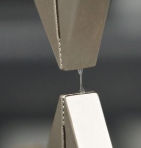
Figure 1: A micro tensile bar in polycarbonate, measuring 100 μm thick.
Micro moulded samples are tested to determine the tensile properties and whether the tiny gates and corresponding high injection pressures cause excessive material shear and property loss. Figure 2 shows micro grippers holding a micro moulded tensile bar based on ASTM standards but geared towards micro moulding. For scaling, the tensile bar length is about the size of the letter ‘I’ on a keyboard.
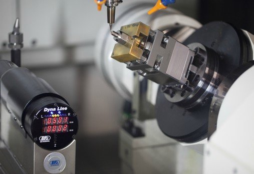
 Figure 2: Five-axis micro milling of micro grippers to 1 μm at Isometric Micro Moulding.
An additional output to the tensile bar testing is actual shrink values. It is common to select the middle of the range for shrink as an educated industry guess. Running the actual part material in the tensile bar mould provides an actual shrink value to use in the mould design. In the event that the parts have single micron tolerances, using a full range of shrink from 10 to 25 μm could contribute to significant steel changes, providing the shrink is estimated incorrectly. Improper shrink prediction can lead to part quality issues and project timeline loss due to mould adjustments/datum error in setup to re-adjust for actual shrink.
The remaining most common mould design criteria listed—namely gate diameter, parting line locations, and ejection style—are to be addressed in an upcoming blog post regarding Challenges in Micro Molding, Part 2. Learn more about Isometric’s micro tooling capabilities here: https://isomicro.com/micro-tooling/.
Originally posted on http://www.cmmmagazine.com/
Powerful micro capabilites that bring your project to life.
Connect with our expert team of plastics engineers today!

USA PHONE +1 715-246-7005 | FAX +1 715-246-3462 | EMAIL [email protected]
240 Wisconsin Drive, New Richmond, WI 54017, USA
Copyright © 2024 Isometric Micro Molding. All Rights Reserved.
ISO Certification 13485: 2016
USA PHONE +1 715-246-7005
FAX +1 715-246-3462
EMAIL [email protected]
240 Wisconsin Drive
New Richmond, WI 54017, USA
Copyright © 2024 Isometric Micro Molding.
All Rights Reserved.
ISO Certification 13485: 2016
Reach out to discuss your project with one of our Micro Molding Experts.